


-
1
-
2
-
3
해당 자료는 1페이지 까지만 미리보기를 제공합니다.
1페이지 이후부터 다운로드 후 확인할 수 있습니다.
1페이지 이후부터 다운로드 후 확인할 수 있습니다.


본문내용
it
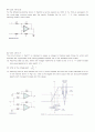
performs as an amplifier whose gain rolls off at the low-frequency end in the manner of a high-pass STC network, and at the high-frequency end in the manner of a low-pass STC network. Design the circuit to provide a gain of 40 dB in the \"middle frequency range\", a low-frequency 3-dB point at 100Hz, a high-frequency 3-dB point at 10kHz, and an input resistance ( at
{ ω}>>{ ω}_{1 }
) of 10㏀.
추천자료
 전자회로 부품의 동작특성
 전자회로 실험 보고서
- 전자회로보고서
- 전자회로실험 - 실험9 에미터 공통 증폭기의 특성(예비 및 결과레포트)
- 전자회로
 전자회로 설계 및 실습 - 예비7 : Diode와 OpAmp를 이용한 AM라디오설계
- 전자회로 설계 및 실습 - 예비8 : Common Source Amplifier 설계
- 전자회로 설계 및 실습 - 예비9 : MOSFET Current Source와 Source Follower설계
- 전자회로 설계 및 실습 - 예비11:CMOS Inverter, Tri-state 설계
- 전기전자기초실습_선로회로
 [전자회로] 전압 분배 바이어스
- 전자회로 및 실험 - Diode Characteristics[예비와 결과 보고서]
- 전자회로실험 - 트렌지스터 직류 바이어스 실험
- 가격1,000원
- 페이지수3페이지
- 등록일2004.06.02
- 저작시기2004.06
- 파일형식한글(hwp)
- 자료번호#253939

본 자료는 최근 2주간 다운받은 회원이 없습니다.


소개글