


-
 1
1
-
 2
2
-
 3
3
-
 4
4
-
 5
5
-
 6
6
-
 7
7
-
 8
8
-
 9
9
-
 10
10
-
 11
11
-
 12
12
-
 13
13
-
 14
14
-
 15
15
-
 16
16
-
 17
17
-
 18
18
-
 19
19
-
 20
20
-
 21
21
-
 22
22
-
 23
23
-
 24
24
-
 25
25
-
 26
26
-
 27
27
-
 28
28
-
 29
29
-
 30
30
-
 31
31
-
 32
32
-
 33
33
-
 34
34
-
 35
35
-
 36
36
-
 37
37
-
 38
38
-
 39
39
-
 40
40
-
 41
41
-
 42
42
-
 43
43
-
 44
44
-
 45
45
-
 46
46
-
 47
47
-
 48
48
-
 49
49
-
 50
50
-
 51
51
-
 52
52
-
 53
53
-
 54
54
-
 55
55
-
 56
56
-
 57
57
-
 58
58
-
 59
59
-
 60
60
-
 61
61
-
 62
62
-
 63
63
-
 64
64
-
 65
65
-
 66
66
-
 67
67
-
 68
68
-
 69
69
-
 70
70
-
 71
71
-
 72
72
-
 73
73
-
 74
74
-
 75
75
-
 76
76
-
 77
77
-
 78
78
-
 79
79
-
 80
80
-
 81
81
-
 82
82
-
 83
83
-
 84
84
-
 85
85
-
 86
86
-
 87
87
-
 88
88
-
 89
89
-
 90
90
-
 91
91
-
 92
92
-
 93
93
-
 94
94
-
 95
95
-
 96
96
-
 97
97
-
 98
98
-
 99
99
-
 100
100
-
101
-
102
-
103
-
104
-
105
-
106
-
107
-
108
-
109
-
110
-
111
-
112
-
113
-
114
-
115
-
116
-
117
-
118
-
119
-
120
-
121
-
122
-
123
-
124
-
125
-
126
-
127
-
128
-
129
-
130
-
131
-
132
-
133
-
134
-
135
-
136
-
137
-
138
-
139
-
140
-
141
-
142
-
143
-
144
-
145
-
146
-
147
-
148
-
149
-
150
-
151
-
152
-
153
-
154
-
155
-
156
-
157
-
158
-
159
-
160
-
161
-
162
-
163
-
164
-
165
-
166
-
167
-
168
-
169
-
170
-
171
-
172
-
173
-
174
-
175
-
176
-
177
-
178
-
179
본 자료는 10페이지 의 미리보기를 제공합니다. 이미지를 클릭하여 주세요.

-
1
-
2
-
3
-
4
-
5
-
6
-
7
-
8
-
9
-
10
-
11
-
12
-
13
-
14
-
15
-
16
-
17
-
18
-
19
-
20
-
21
-
22
-
23
-
24
-
25
-
26
-
27
-
28
-
29
-
30
-
31
-
32
-
33
-
34
-
35
-
36
-
37
-
38
-
39
-
40
-
41
-
42
-
43
-
44
-
45
-
46
-
47
-
48
-
49
-
50
-
51
-
52
-
53
-
54
-
55
-
56
-
57
-
58
-
59
-
60
-
61
-
62
-
63
-
64
-
65
-
66
-
67
-
68
-
69
-
70
-
71
-
72
-
73
-
74
-
75
-
76
-
77
-
78
-
79
-
80
-
81
-
82
-
83
-
84
-
85
-
86
-
87
-
88
-
89
-
90
-
91
-
92
-
93
-
94
-
95
-
96
-
97
-
98
-
99
-
100
-
101
-
102
-
103
-
104
-
105
-
106
-
107
-
108
-
109
-
110
-
111
-
112
-
113
-
114
-
115
-
116
-
117
-
118
-
119
-
120
-
121
-
122
-
123
-
124
-
125
-
126
-
127
-
128
-
129
-
130
-
131
-
132
-
133
-
134
-
135
-
136
-
137
-
138
-
139
-
140
-
141
-
142
-
143
-
144
-
145
-
146
-
147
-
148
-
149
-
150
-
151
-
152
-
153
-
154
-
155
-
156
-
157
-
158
-
159
-
160
-
161
-
162
-
163
-
164
-
165
-
166
-
167
-
168
-
169
-
170
-
171
-
172
-
173
-
174
-
175
-
176
-
177
-
178
-
179
해당 자료는 10페이지 까지만 미리보기를 제공합니다.
10페이지 이후부터 다운로드 후 확인할 수 있습니다.
10페이지 이후부터 다운로드 후 확인할 수 있습니다.


목차
없음
본문내용
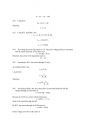
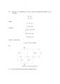
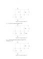
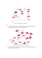
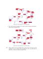
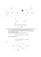
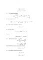
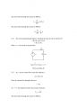
2.1 Current source
2.2 Voltage source
2.3 Resistor
2.4 Capacitor
2.5 Inductor
Section 2.2 Charge and Current
2.6 b)
The current direction is designated as the direction of the movement of positive
charges.
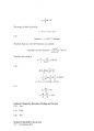
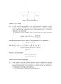
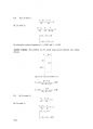
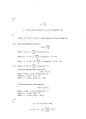
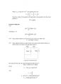
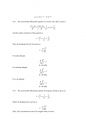
2.7 The relationship of charge and current is
( ) ( ) ( ) 0
0
q t i t dt q t
t
t
= ∫ +
so
( ) ( ) ( ) 0
0
q t 2sin 10 t dt q t
t
t
= ∫ π +
( ) ( ) ( ) 0 cos 10
10
2
0
q t t q t
t
t
+ ⎥ ⎦
⎤
⎢ ⎣
⎡ −
= π
π
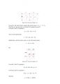
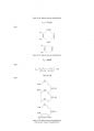
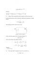
2.8 The coulomb of one electron is denoted by e and
( ) ( ) ( ) 0
0
q t i t dt q t
t
t
= ∫ +
So
( ) ( ) 0
0
( ) / 1 12t dt q t
e
n t q t e
t
t
= = ∫ +
If t0 = 0 and ( ) 0 q t0 = ,
( ) 6 t2
e
n t =
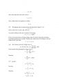
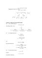
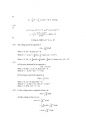
2.9
q(t)= ∫idt
q(t) dt
t
= ∫
0
5
q(t)= 5t
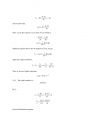
2.10
( ) 5[5 ] 5(5) 5(0) 25
q t =0 t = − = Coulombs
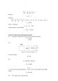
2.11 Using the definition of current-charge relationship, the equation can be rewritten
as:
e
t
n
dt
i dq
Δ
Δ
= =
Thus, the current flow within t1 and t2 time interval is,
i ( 1.6 10 ) 3A
2
(5.75 2) 10 19
19
− × = −
− ×
= −
The negative sign shows the current flow in the opposite direction with respect to the
electric charge.
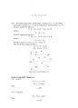
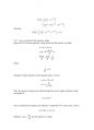
2.12 Assuming the area of the metal surface is S, The mass of the nickel with depth d
= 0.15mm is
m = ρ × d × S
Meanwhile, using the electro-chemical equivalent, the mass of the nickel can be
expressed as
m = k × I × t
where I = σ × S.
Equating the two expressions of the mass, the coating time is found:
t = ρ × d / σ = 1.24 × 10⁵ s ≈ 34.4 hour
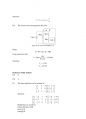
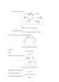
Section 2.3 Voltage
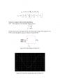
2.13 By the definition of voltage, when a positive charge moves from high voltage to
low voltage, its potential energy decreases.
So a is “+”, b is “-”. In other words, uab=1V.
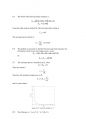
2.14 The current i(t) is defined as:
( )
⎭ ⎬ ⎫
⎩ ⎨ ⎧
< ≤
=
elsewhere
t
i t
0
3 0 1
Therefore, the charge is
3 3
1
0 ∫
g = dt = C
The energy in Joules is given by:
J =V ×C = 5×3 =15J
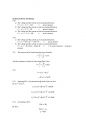
2.15
1 electron = 1.6 10−19 − × Coulombs.
Therefore, there are 6.25×10¹⁸ electrons in a coulomb.
Coulombs of5×1016 electrons = 3
18
16
8 10
6.25 10
5 10 − = ×
×
×
Therefore, the voltage is
1875
8 10
15
3 =
×
= = C −
V J V
2.16
( ) dt t t q ⎟
2.2 Voltage source
2.3 Resistor
2.4 Capacitor
2.5 Inductor
Section 2.2 Charge and Current
2.6 b)
The current direction is designated as the direction of the movement of positive
charges.
2.7 The relationship of charge and current is
( ) ( ) ( ) 0
0
q t i t dt q t
t
t
= ∫ +
so
( ) ( ) ( ) 0
0
q t 2sin 10 t dt q t
t
t
= ∫ π +
( ) ( ) ( ) 0 cos 10
10
2
0
q t t q t
t
t
+ ⎥ ⎦
⎤
⎢ ⎣
⎡ −
= π
π
2.8 The coulomb of one electron is denoted by e and
( ) ( ) ( ) 0
0
q t i t dt q t
t
t
= ∫ +
So
( ) ( ) 0
0
( ) / 1 12t dt q t
e
n t q t e
t
t
= = ∫ +
If t0 = 0 and ( ) 0 q t0 = ,
( ) 6 t2
e
n t =
2.9
q(t)= ∫idt
q(t) dt
t
= ∫
0
5
q(t)= 5t
2.10
( ) 5[5 ] 5(5) 5(0) 25
q t =0 t = − = Coulombs
2.11 Using the definition of current-charge relationship, the equation can be rewritten
as:
e
t
n
dt
i dq
Δ
Δ
= =
Thus, the current flow within t1 and t2 time interval is,
i ( 1.6 10 ) 3A
2
(5.75 2) 10 19
19
− × = −
− ×
= −
The negative sign shows the current flow in the opposite direction with respect to the
electric charge.
2.12 Assuming the area of the metal surface is S, The mass of the nickel with depth d
= 0.15mm is
m = ρ × d × S
Meanwhile, using the electro-chemical equivalent, the mass of the nickel can be
expressed as
m = k × I × t
where I = σ × S.
Equating the two expressions of the mass, the coating time is found:
t = ρ × d / σ = 1.24 × 10⁵ s ≈ 34.4 hour
Section 2.3 Voltage
2.13 By the definition of voltage, when a positive charge moves from high voltage to
low voltage, its potential energy decreases.
So a is “+”, b is “-”. In other words, uab=1V.
2.14 The current i(t) is defined as:
( )
⎭ ⎬ ⎫
⎩ ⎨ ⎧
< ≤
=
elsewhere
t
i t
0
3 0 1
Therefore, the charge is
3 3
1
0 ∫
g = dt = C
The energy in Joules is given by:
J =V ×C = 5×3 =15J
2.15
1 electron = 1.6 10−19 − × Coulombs.
Therefore, there are 6.25×10¹⁸ electrons in a coulomb.
Coulombs of5×1016 electrons = 3
18
16
8 10
6.25 10
5 10 − = ×
×
×
Therefore, the voltage is
1875
8 10
15
3 =
×
= = C −
V J V
2.16
( ) dt t t q ⎟
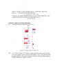
추천자료
 건축 의학 전기.전자 광물(돌)의 이용
- 부동소수점 미국전기전자공학회(IEEE)754
- 1교시 <방사선 이론> 전기전자공학
- [예비] 전기전자실험 커패시터의 직병렬 연결
- [예비] 전기전자실험 인덕터의 직병렬 연결
- [기초전자전기] 모터 제어 실험 보고서
- [전기전자실험] RC RL 주파수응답
- [전기전자실험] RLC 공진회로
- [기초 전기전자] 전류, 전압 측정
 [전자전기설계실험 03] 06주차 (결과) 다이오드 회로 - 정류 회로 설계 (Diode Circuit &...
- [전자전기설계실험 03] 07주차 (결과) 연산 증폭기 & 다이오드 (Operational Amplifier &...
- [전기전자 기초실험] 역률 측정 실험
- [전자전기컴퓨터설계실험3] N-Channel MOSFET 전류/전압 특성 측정 결과보고서 (About MOSFET...
- [전자전기컴퓨터설계실험3] MOSFET Circuit &#8211; Basic MOSFET Circuit 결과보고서 (A...
- 가격10,000원
- 페이지수179페이지
- 등록일2014.10.01
- 저작시기2013.2
- 파일형식아크로뱃 뷰어(pdf)
- 자료번호#939603

본 자료는 최근 2주간 다운받은 회원이 없습니다.


소개글