


-
1
-
2
-
3
-
4
-
5
-
6
-
7
-
8
해당 자료는 2페이지 까지만 미리보기를 제공합니다.
2페이지 이후부터 다운로드 후 확인할 수 있습니다.
2페이지 이후부터 다운로드 후 확인할 수 있습니다.


목차
1. 서론
2. 연구 방법
2. 1. 형광 X 선에 의한 부착량 및 조성 측정 방법
2.2. 표준 시료 제조
2.3. 표준 시료의 도금 부착량과 조성 분석
3. 실험 결과
3.1. 표준 시료의 부착량 및 조성 편차
3.2. 표준 시료의 표면 특성
3.3. XRF에 의한 검량선 작성
4. 결론
5. 참고 문헌
2. 연구 방법
2. 1. 형광 X 선에 의한 부착량 및 조성 측정 방법
2.2. 표준 시료 제조
2.3. 표준 시료의 도금 부착량과 조성 분석
3. 실험 결과
3.1. 표준 시료의 부착량 및 조성 편차
3.2. 표준 시료의 표면 특성
3.3. XRF에 의한 검량선 작성
4. 결론
5. 참고 문헌
본문내용
이 기대되며, 도금 제품의 품질 확보에 기여 할 수 있으리라 판단된다.
5. 참고 문헌
(1) R. Tertian and F. Claisse, Principles of quantitative X-ray fluorescence analysis, Heyden & Son Ltd, 1982.
(2) K. Tsumura and S. Oshiba, 鐵と鋼, Vol 7, 1170, 1977.
(3) 신광수, 홍기정, 박병학, 전기도금강판의 합금층 분석 연구, RIST 연구결과보고서, 1988.
(4) C. Whiston, X-ray methods, Joh, Wiley & Sons, pp268-279, 1987.
(5) D. Laguitton and W. Parrish, Anal. chem. Vol.49, No.8, 1152, 1977.
(6) J.F. Butler, J. vac. sci. & technol., Vol.7, No.1, S52.
(7) 이영호, 측정 표준 Vol. 17, No.4, 56, 1994.
Figure and photo caption
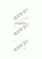
Fig. 1 X-ray flourescence from coating
Fig. 2 Auger depth profiles of Zn-Fe coated samples
Fig. 3 Zn XRF intensity as a function of coating weight
Fig. 4 Comparision of coating weight measured by chemical vs XRF method
Fig. 5 Comparision of coating weight measured by chemical vs XRF method
Fig. 6 Zn Kα and Zn Lα intensity as a function of coating weight
Fig. 7 Zn Lα intensity as a function of coating weight
Photo 1 Photograph of standard reference samples
Photo 2 Selected SEM image of Zn coated samples(coating weight increases as a to d)
Photo 3 Selected SEM image of Zn-Fe coated samples (coating weight increases as a to d)
X-ray Zn Lα Zn Kα
Fe Kα
θ
Zn(A) t
Fe(B)
Figure and photo caption
Fig. 1 X-ray flourescence from coating
Fig. 2 Auger depth profiles of Zn-Fe coated samples
Fig. 3 Zn XRF intensity as a function of coating weight
Fig. 4 Comparision of coating weight measured by chemical vs XRF method
Fig. 5 Comparision of coating weight measured by chemical vs XRF method
Fig. 6 Zn Kα and Zn Lα intensity as a function of coating weight
Fig. 7 Zn Lα intensity as a function of coating weight
Photo 1 Photograph of standard reference samples
Photo 2 Selected SEM image of Zn coated samples
Photo 3 Selected SEM image of Zn-Fe coated samples
5. 참고 문헌
(1) R. Tertian and F. Claisse, Principles of quantitative X-ray fluorescence analysis, Heyden & Son Ltd, 1982.
(2) K. Tsumura and S. Oshiba, 鐵と鋼, Vol 7, 1170, 1977.
(3) 신광수, 홍기정, 박병학, 전기도금강판의 합금층 분석 연구, RIST 연구결과보고서, 1988.
(4) C. Whiston, X-ray methods, Joh, Wiley & Sons, pp268-279, 1987.
(5) D. Laguitton and W. Parrish, Anal. chem. Vol.49, No.8, 1152, 1977.
(6) J.F. Butler, J. vac. sci. & technol., Vol.7, No.1, S52.
(7) 이영호, 측정 표준 Vol. 17, No.4, 56, 1994.
Figure and photo caption
Fig. 1 X-ray flourescence from coating
Fig. 2 Auger depth profiles of Zn-Fe coated samples
Fig. 3 Zn XRF intensity as a function of coating weight
Fig. 4 Comparision of coating weight measured by chemical vs XRF method
Fig. 5 Comparision of coating weight measured by chemical vs XRF method
Fig. 6 Zn Kα and Zn Lα intensity as a function of coating weight
Fig. 7 Zn Lα intensity as a function of coating weight
Photo 1 Photograph of standard reference samples
Photo 2 Selected SEM image of Zn coated samples(coating weight increases as a to d)
Photo 3 Selected SEM image of Zn-Fe coated samples (coating weight increases as a to d)
X-ray Zn Lα Zn Kα
Fe Kα
θ
Zn(A) t
Fe(B)
Figure and photo caption
Fig. 1 X-ray flourescence from coating
Fig. 2 Auger depth profiles of Zn-Fe coated samples
Fig. 3 Zn XRF intensity as a function of coating weight
Fig. 4 Comparision of coating weight measured by chemical vs XRF method
Fig. 5 Comparision of coating weight measured by chemical vs XRF method
Fig. 6 Zn Kα and Zn Lα intensity as a function of coating weight
Fig. 7 Zn Lα intensity as a function of coating weight
Photo 1 Photograph of standard reference samples
Photo 2 Selected SEM image of Zn coated samples
Photo 3 Selected SEM image of Zn-Fe coated samples
추천자료
- 가격1,300원
- 페이지수8페이지
- 등록일2002.03.07
- 저작시기2002.03
- 파일형식한글(hwp)
- 자료번호#191707

본 자료는 최근 2주간 다운받은 회원이 없습니다.

- 편집

- 내용
- 가격


소개글