


-
1
-
2
-
3
-
4
-
5
-
6
-
7
-
8
-
9
-
10
-
11
-
12
-
13
-
14
-
15
해당 자료는 5페이지 까지만 미리보기를 제공합니다.
5페이지 이후부터 다운로드 후 확인할 수 있습니다.
5페이지 이후부터 다운로드 후 확인할 수 있습니다.


목차
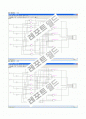
(1) Derive a truth table for the problem. 7세그먼트 진리표
(2) Use Karnaugh maps to derive logic equations in sum-of-products or product-of-sums form depending on whether NAND gates or NOR gates are required. 카노맵구현
(3) Enter the truth table into LogicAid, derive the logic equations, and check the answers against the results of step (2). 회로 식 유도
(4) Draw a circuit of AND and OR gates, trying to minimize the number of gates required by using common gates where appropriate. Factoring or multiplying out is required in some cases. 회로도 구현
(5) Convert to NAND or NOR gates as specified. nand ,nor 로 구현한 회로도
본문내용
2009년 2학기
과목: 디지털공학
프로젝트 #1
분 반
라
조 번호
6조
조 원
학 번
이 름
조별 성적
개인 성적
총점
20062666
김 현 철
20092682
김 효 천
20062675
남 종 현
20082689
박 해 은
- 40 points
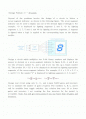
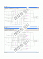
Several of the problems involve the design of a circuit to derive a seven-segment indicator, as shown in the following figure. The seven-segment indicator can be used to display any one of the decimal digits 0 through 9. For example, \"1\" is displayed by lighting segments 2 and 3, \"2\" by lighting segments 1, 2, 7, 5 and 4, and \"8\" by lighting all seven segments. A segment is lighted when a logic is applied to the corresponding input on the display module.
Design a circuit which multiplies two 2-bit binary numbers and displays the answer in decimal on a seven-segment indicator. In figure 8-24, A and B are teo bits of binary number N1, and C and D are two bits og a binary number N2. The product (N1 * N2) is to be displayed in decimal but lighting appropriate segments of the seven-segment indicator. For example, if A = 1, B = 0, C = 1, and D = 0, the number \"4\" is displayed by lighting segments 2, 3, 6, and 7.
Design your circuit using only 2-, 3-, and 4-input NAND gates and inverters. Try to minimize the number of gates required. The variables A, B, C, and D will be available from toggle switches. Any solution that uses 18 or fewer gates and inverters ( not counting the four inverters for the inputs) is acceptable. Note: You will get extra points if you use fewer than 18 gates and inverters.
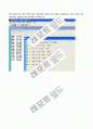
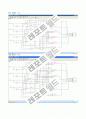
(1) Derive a truth table for the problem.
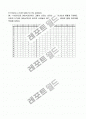
(N1 * N2)이므로 (AB2*CD2)이다 그래서 나오는 숫자는 0,1,2,3,4,6,9 이렇게 7개이다. 나머지 5,7,8은 (AB2*CD2)의 곱으로 나타낼수 없다. 위와 같은 결과로 밑에 진리표를 작성해 보았다.
A
B
C
D
X1
X2
X3
X4
X5
X6
X7
0
0
0
0
0
1
1
1
1
1
1
0
0
0
0
0
1
1
1
1
1
1
1
0
0
0
0
1
0
1
1
1
1
1
1
0
0
0
0
1
1
1
1
1
1
1
1
0
0
0
1
0
0
1
1
1
1
1
1
0
1
0
1
0
1
0
1
1
0
0
0
0
2
0
1
1
0
1
1
0
1
1
0
1
3
0
1
1
1
1
1
1
1
0
0
1
0
1
0
0
0
1
1
1
1
1
1
0
2
1
0
0
1
1
1
0
1
1
0
1
4
1
0
1
0
0
1
1
0
0
1
1
6
1
0
1
1
1
0
1
1
1
1
1
0
1
1
0
0
1
1
1
1
1
1
0
3
1
1
0
1
1
1
1
1
0
0
1
6
1
1
1
0
1
0
1
1
1
1
1
9
1
1
1
1
1
1
1
1
0
1
1
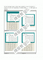
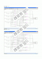
(2) Use Karnaugh maps to derive logic equations in sum-of-products or product-of-sums form depending on whether NAND gates or NOR gates are required.
Output X1
Outout X2
Output X3
Output X4
Output X5
Output X6
Output X7
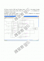
(3) Enter the truth table into LogicAid, derive the logic equations, and check the answers against the results of step (2).
(4) Draw a circuit of AND and OR gates, trying to minimize the number of gates required by using common gates where appropriate. Factoring or multiplying out is required in some cases.
AND게이트 10개 OR게이트 6개로 구현했습니다. 처음에는 OR게이트가 7개 나왔는데 X1과 X4가 같은식이라 하나를 줄일수 있었다.
(5) Convert to NAND or NOR gates as specified.
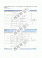
(6) Simulate your answer to (5) using SimUaid, and verify that the circuit works correctly.
1) ABCD=0000 -0
2)0001 - 0
3) 0010 - 0
4) 0011 - 0
5) 0100 - 0
6) 0101 - 1
7) 0110 - 2
8) 0111 - 3
9) 1000 - 0
10) 1001 - 2
11) 1010 - 4
12) 1011 - 6
13) 1100 - 0
14) 1101 - 3
15) 1110 - 6
16) 1111 - 9
과목: 디지털공학
프로젝트 #1
분 반
라
조 번호
6조
조 원
학 번
이 름
조별 성적
개인 성적
총점
20062666
김 현 철
20092682
김 효 천
20062675
남 종 현
20082689
박 해 은
Several of the problems involve the design of a circuit to derive a seven-segment indicator, as shown in the following figure. The seven-segment indicator can be used to display any one of the decimal digits 0 through 9. For example, \"1\" is displayed by lighting segments 2 and 3, \"2\" by lighting segments 1, 2, 7, 5 and 4, and \"8\" by lighting all seven segments. A segment is lighted when a logic is applied to the corresponding input on the display module.
Design a circuit which multiplies two 2-bit binary numbers and displays the answer in decimal on a seven-segment indicator. In figure 8-24, A and B are teo bits of binary number N1, and C and D are two bits og a binary number N2. The product (N1 * N2) is to be displayed in decimal but lighting appropriate segments of the seven-segment indicator. For example, if A = 1, B = 0, C = 1, and D = 0, the number \"4\" is displayed by lighting segments 2, 3, 6, and 7.
Design your circuit using only 2-, 3-, and 4-input NAND gates and inverters. Try to minimize the number of gates required. The variables A, B, C, and D will be available from toggle switches. Any solution that uses 18 or fewer gates and inverters ( not counting the four inverters for the inputs) is acceptable. Note: You will get extra points if you use fewer than 18 gates and inverters.
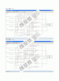
(1) Derive a truth table for the problem.
(N1 * N2)이므로 (AB2*CD2)이다 그래서 나오는 숫자는 0,1,2,3,4,6,9 이렇게 7개이다. 나머지 5,7,8은 (AB2*CD2)의 곱으로 나타낼수 없다. 위와 같은 결과로 밑에 진리표를 작성해 보았다.
A
B
C
D
X1
X2
X3
X4
X5
X6
X7
0
0
0
0
0
1
1
1
1
1
1
0
0
0
0
0
1
1
1
1
1
1
1
0
0
0
0
1
0
1
1
1
1
1
1
0
0
0
0
1
1
1
1
1
1
1
1
0
0
0
1
0
0
1
1
1
1
1
1
0
1
0
1
0
1
0
1
1
0
0
0
0
2
0
1
1
0
1
1
0
1
1
0
1
3
0
1
1
1
1
1
1
1
0
0
1
0
1
0
0
0
1
1
1
1
1
1
0
2
1
0
0
1
1
1
0
1
1
0
1
4
1
0
1
0
0
1
1
0
0
1
1
6
1
0
1
1
1
0
1
1
1
1
1
0
1
1
0
0
1
1
1
1
1
1
0
3
1
1
0
1
1
1
1
1
0
0
1
6
1
1
1
0
1
0
1
1
1
1
1
9
1
1
1
1
1
1
1
1
0
1
1
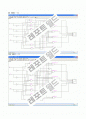
(2) Use Karnaugh maps to derive logic equations in sum-of-products or product-of-sums form depending on whether NAND gates or NOR gates are required.
Output X1
Outout X2
Output X3
Output X4
Output X5
Output X6
Output X7
(3) Enter the truth table into LogicAid, derive the logic equations, and check the answers against the results of step (2).
(4) Draw a circuit of AND and OR gates, trying to minimize the number of gates required by using common gates where appropriate. Factoring or multiplying out is required in some cases.
AND게이트 10개 OR게이트 6개로 구현했습니다. 처음에는 OR게이트가 7개 나왔는데 X1과 X4가 같은식이라 하나를 줄일수 있었다.
(5) Convert to NAND or NOR gates as specified.
(6) Simulate your answer to (5) using SimUaid, and verify that the circuit works correctly.
1) ABCD=0000 -0
2)0001 - 0
3) 0010 - 0
4) 0011 - 0
5) 0100 - 0
6) 0101 - 1
7) 0110 - 2
8) 0111 - 3
9) 1000 - 0
10) 1001 - 2
11) 1010 - 4
12) 1011 - 6
13) 1100 - 0
14) 1101 - 3
15) 1110 - 6
16) 1111 - 9
추천자료
 [전자공학실험] 디지털실험-가산기 결과레포트
- 디지털 시대의 의공학의 미래 전망
- [전자공학실험] 회로의간소화및 EX-OR회로
- 전자공학실험 동조회로 실험보고서 < 동조회로 (Tank회로) >
- 5. 전기공학실험 병렬 회로
- 4. 전기공학실험 직렬 회로
- [전기공학실험] 회로 정리와 변환
- 전기공학실험 R-L-C 병렬공진회로
- [전자공학실험] 예비보고서 02장 - 신호와 잡음, 그리고 접지 : 전기신호를 다루는 회로실험...
- [디지털 공학 실험] (예비) 05장 인코더(Encoder)/ 디코더(Decoder)와 멀티플렉서(Mux)/ 디멀...
- 전자공학 논리회로 실험 - Logic 연산과 Gates
- 기초공학실험 - 디지털 오실로스코프를 이용한 파형측정과 데이터 획득
- 전자공학 실험 - 논리 게이트의 특성 및 연산회로
- rc교류회로,전기공학 실험 사전보고서
- 가격2,000원
- 페이지수15페이지
- 등록일2010.01.18
- 저작시기2009.11
- 파일형식한글(hwp)
- 자료번호#575451

본 자료는 최근 2주간 다운받은 회원이 없습니다.


소개글