


|
디지털회로인데 A만을 입력으로 사용하였다. 1. 실험목적
● Digital Gate의 IC를 구현하는 방법을 익힌다.
● Flip-flip을 구성하고 동작 원리를 이해한다.’
2. 실험결과
1) 실험 1 : Digital Gate (OR, AND, NOT, EX-OR Gate)
2) 실험 2 : D Flip-flo
|
|
|
Circuits,\" vol. 32, no. 5, pp. 730-735, 1997.
[4] Philipus Oh, Win Chaivipas, Akira Matsuzawn, “A study on Full Digital Clock Data Recovery”
[5] YIREN, “Design of a clock and data recovery circuit in 65 NM technology”
[6] Sagar Waghela, San Jose State University, “PLL based CDR using Calibrated Del
|
|
|
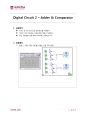
Digital Circuit 2 – Adder & Comparator
1.실험목적
2.실험결과
1)실험 1 : 7483, 7485, 7447를 이용한 단일 FND 출력
3.고 찰
Digital Circuit 3 – Adder & Comparator
4.실험목적
5.실험결과
1)실험 2 : 0~14까지의 숫자를 FND에 10의자리와 1의자리 출
|
|
|
, K가 1이면 reset이므로 J의 input은 “don\'t care”로 처리한다. 이 1에서 변하지 않을 때는 J의 input은 “don\'t care”, K는 1이다.
Step 4:Karnaugh Maps
이제 Next-State Table과 Flip-Flop Transition Table을 이용해 Karnaugh Maps을 그릴 수 있다. Karnaugh Maps을 그릴 때, 빨
|
|

|
.1 IC Logic Family Operation and Characteristics
Digital logic circuits can be classified as belonging to one of two categories, either combinational (also called
combinatorial) or sequential logic circuits. The output logic level of a combinatorial circuit depends only on
the current logic levels p
|
|
 |
Circuit를 목표로 한다.
References
[1] KETI 주간전자정보 “ 유기EL개발 동향과 향후전망 ”2000
[2] 중소기업청 해외벤처넷 http://global.smba.go.kr/market/analysis/tech
[3] (주)엘리아테크 유기EL Researcher http://www.eliatech.com/
[4] C.Adachi, H.Tokailin, H.Higashi and T.Kusumot
|
|
|
Circuit Voltage)을 측정하여 미리 측정된 OCV에 대한 배터리 잔존용량 값을 Table화 하여 배터리 잔존용량(SOC:State of Charge)값과 비교하여 보정하는 알고리즘이다.
3.4.6 Battery 과전압 보호 제어
BMS(Battery Management System)는 기존의 디지털 신호에 의해 과
|
|
 |
디지털 논리 회로 (Digital Logic Circuits)
□ 기본 논리 게이트(AND, OR, NOT, NAND, NOR, XOR, XNOR)의 진리표를 작성하시오.
□ 플립플롭(flip-flop)의 종류와 그 동작 원리를 설명하시오.
□ 레지스터와 시 <제목 차례>
? 이 자료를 구성하면서 읽어본 참
|
|
 |
Circuit Theory) 19
2. 전자기학 (Electromagnetics) 19
3. 반도체 소자 (Semiconductor Devices) 20
4. 디지털 논리 회로 (Digital Logic Circuits) 21
5. 신호 및 시스템 (Signals and Systems) 22
6. 제어 이론 (Control Theory) 22
7. 신호처리 (Signal Processing) 23
9. Microprocessors and Embed
|
|