


-
1
-
2
-
3
-
4
-
5
-
6
-
7
-
8
-
9
-
10
-
11
-
12
-
13
-
14
-
15
해당 자료는 5페이지 까지만 미리보기를 제공합니다.
5페이지 이후부터 다운로드 후 확인할 수 있습니다.
5페이지 이후부터 다운로드 후 확인할 수 있습니다.


목차
Chapter 7. Lead Compensator Design
Response
1. OBJECT
2. DISCUSSION
Chapter 8. Lag Compensator Design
1. OBJECT
2. DISCUSSTION
Response
1. OBJECT
2. DISCUSSION
Chapter 8. Lag Compensator Design
1. OBJECT
2. DISCUSSTION
본문내용
Chapter 7. Lead Compensator Design
1.OBJECT
- Learn how to design a lead compensator based on the root locus theory.
- Observe the change of the lead compensator applied to the inverted pendulum motor.
- Carry out the position control of the inverted pendulum motor by using a lead compensator.
2. DISCUSSION
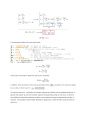
Unit feedback closed loop transfer function is as follow:
(R(s)-Y(s))*KL(s) = Y(s)
Y(s)(1+KL(s)) = KL(s)*R(s)
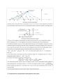
In order to obtain the transfer function of the inverted pendulum with the pendulum removed, we perform the following procedure.
Motor equation
< 중략 >
Chapter 8. Lag Compensator Design
1.OBJECT
- Based on the root locus theory, learn how to design the lag compensator
- After the design, observe the changes that occur when applying the lag compensator to the inverted pendulum motor.
-Perform the position control of the inverted pendulum motor using the backlash compensation.
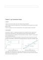
2. DISCUSSION
As described in chapter 7, an appropriate compensator can be added to produce a response that could not exist on the existing loci. These responses are either improved transient response or improved steady state error. Especially, the lag compensator discussed in chapter 8 is mainly used to improve the steady state error.
The steady-state error is the difference between the input and the output for a given test input when sufficient time has elapsed. These test inputs are basically step input, ramp input, and parabolic input.
1.OBJECT
- Learn how to design a lead compensator based on the root locus theory.
- Observe the change of the lead compensator applied to the inverted pendulum motor.
- Carry out the position control of the inverted pendulum motor by using a lead compensator.
2. DISCUSSION
Unit feedback closed loop transfer function is as follow:
(R(s)-Y(s))*KL(s) = Y(s)
Y(s)(1+KL(s)) = KL(s)*R(s)
In order to obtain the transfer function of the inverted pendulum with the pendulum removed, we perform the following procedure.
Motor equation
< 중략 >
Chapter 8. Lag Compensator Design
1.OBJECT
- Based on the root locus theory, learn how to design the lag compensator
- After the design, observe the changes that occur when applying the lag compensator to the inverted pendulum motor.
-Perform the position control of the inverted pendulum motor using the backlash compensation.
2. DISCUSSION
As described in chapter 7, an appropriate compensator can be added to produce a response that could not exist on the existing loci. These responses are either improved transient response or improved steady state error. Especially, the lag compensator discussed in chapter 8 is mainly used to improve the steady state error.
The steady-state error is the difference between the input and the output for a given test input when sufficient time has elapsed. These test inputs are basically step input, ramp input, and parabolic input.
추천자료
 [부산대학교 기계공학응용실험] 모터제어실험 PLC 응용실험 & 모터의 종류, 모터의 구조,...
- 전기공학실험 위상전력제어 실험 예비 레포트
 연세대학교 전력 및 제어공학실험 제어실험 5주차 ELECTRIC POWER AND CONTROL ENGINEERING L...
- 연세대학교 전력 및 제어공학 실험 제어파트 2주차 ELECTRIC POWER AND CONTROL ENGINEERING ...
- 연세대학교 전력 및 제어공학 실험 제어파트 1주차 ELECTRIC POWER AND CONTROL ENGINEERING ...
- 연세대학교 전력 및 제어공학 실험 chapter27-30ELECTRIC POWER AND CONTROL ENGINEERING LAB...
- 연세대학교 전력 및 제어공학 실험 chapter23-26 ELECTRIC POWER AND CONTROL ENGINEERING LA...
- 연세대학교 전력 및 제어공학 실험 chapter36-38 ELECTRIC POWER AND CONTROL ENGINEERING LA...
- 연세대학교전력및제어공학실험 제어프로젝트
- 가격10,000원
- 페이지수15페이지
- 등록일2018.12.16
- 저작시기2018.11
- 파일형식기타(docx)
- 자료번호#1074400

본 자료는 최근 2주간 다운받은 회원이 없습니다.


소개글